Multi Purpose Vehicle

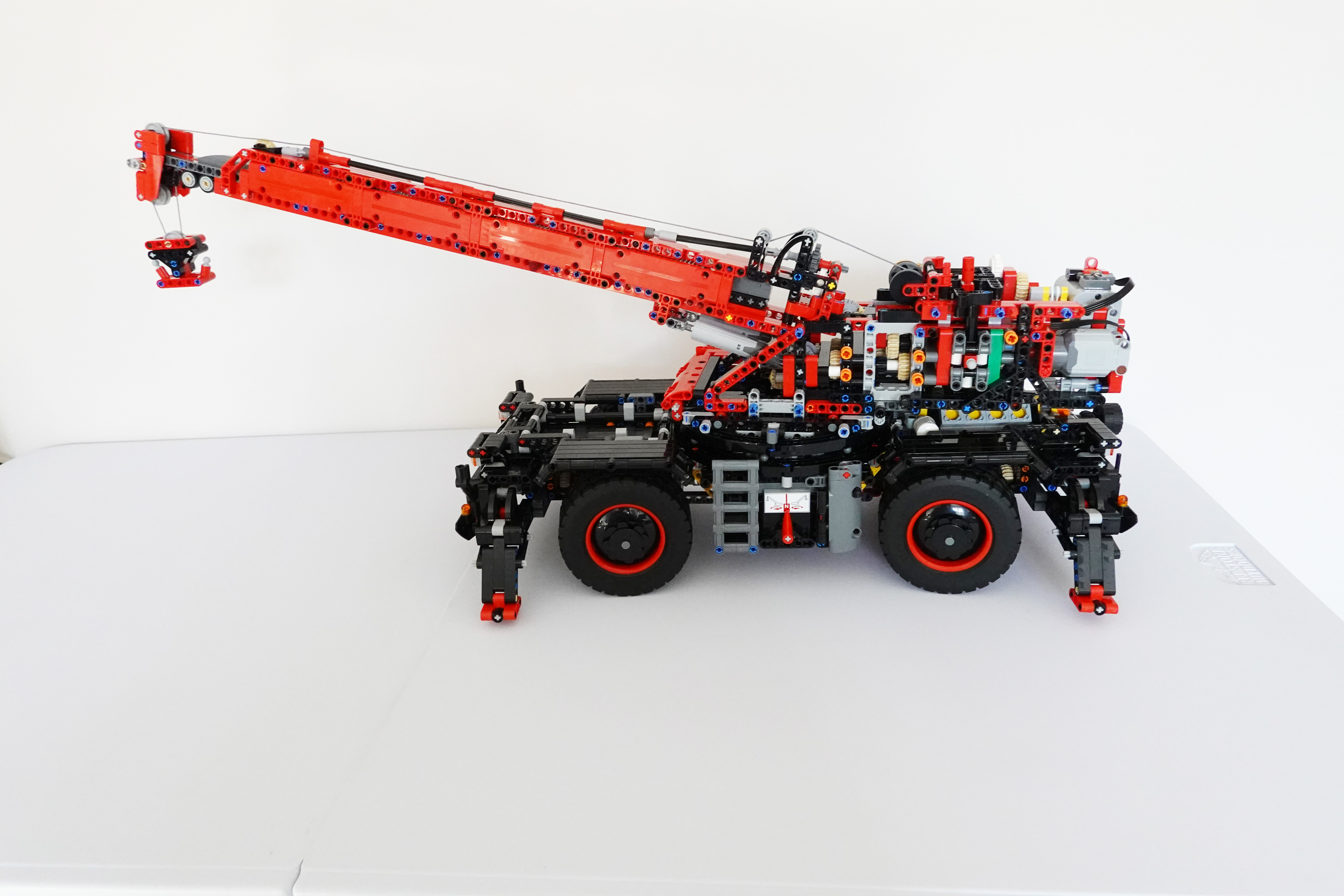
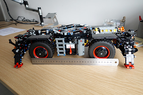
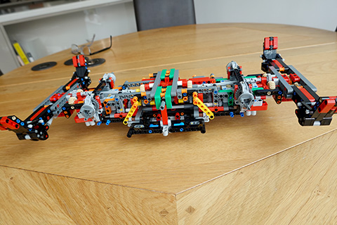
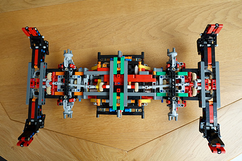
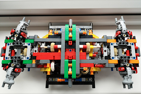
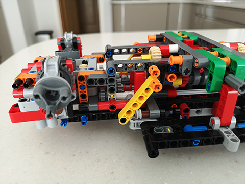
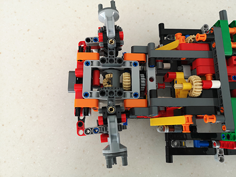
Here is the latest Lego project. It is a fully programmable, remote controlled, vehicle which has steering, photo sensors, and can fire harpoons. The video below shows some of its features.

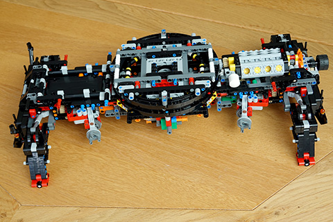
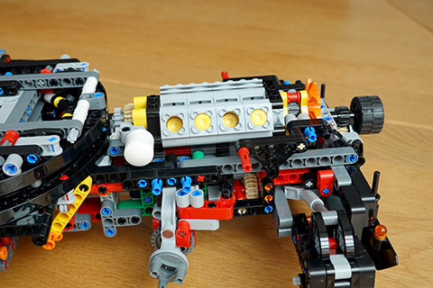
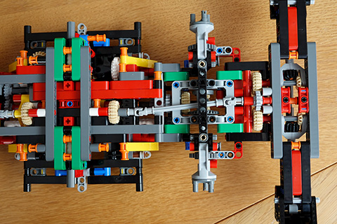
The computer module is the block at the rear into which all the cables from the motors and sensors connect. I have used the same programming language that you are using for your Lego Boost robots. There is lots more we can do with simple robots like this.

Using A Drone

Most of the video used to record my adventures is taken using a drone. So here is an example of my drones and how they are used.

First a video of how the drone flies. You can see that it hovers in place unless told to move, up/down, left/right, forward/backward, or rotate in place. The little white box on the front of the drone is the camera that can take pictures or video.


Now we will see an example of the video taken by the drone as it moves.

The Crane is finished!

The Lego Crane is finally complete and seems to work perfectly. Amazing as I have 9 pieces left over. Here are the photos and videos to prove it. On some devices it may take a little while for the videos to load and automatically run.

Finished Crane

Click on the photo to see a larger image. The wheels rotate and steer, the jib rises and extends, the hook rises and lowers, the crane turret rotates through 360 degrees and the legs rise and lower.


Controls

There are 6 clutches used to assign the single motor to each of parts that move. Each clutch has 3 positions, forward, neutral, and reverse. This photo shows 4 of the clutch controls.


Stabiliser Legs

Click on the image to see the legs lowered.


Rotate the Crane

Click on the image to see the whole top of the crane rotate.


Raising the Jib

Click on the image to see the jib raise.


Extending the Jib

Click on the image to see the jib extend.


Driver’s Cab

And a final image of the driver’s cab. Note the fire extinguisher just behind the cab door.


What next then?

Stage 8

The crane jib has been added and there is only one more stage to go before the model is finished.

Penultimate Stage

The main crane jib has been added and all that is left to do is install the bodywork.

Click on the photo to see a larger version.


This is BIG!

Me holding the stage 8 build to give you some feeling for the size of the crane.

Stage 7

With stage 7 of the build the whole thing is starting to look like a crane. Fitting the crane body to the undercarriage was tricky.

Top View

At the very top, in the middle, you can just see the crane winch with its reel of cable. Well it is actually cord of course.


Side View

I have tested the motor and the various clutch drives and everything seems to work. But all my fingers are crossed.

The main clutch mechanism consists of three clutches side by side. The control lever slides left and right through three clutch positions. In each position it can be in neutral, or move forward or backward to engage gears.


Rear View

Note the electric motor and battery holder mounted on the back of the crane unit.


Stage 6 Details

These photos show some of the details of stage 6 of the build. In particular lots of gears, including some differential gearing.

Stage 6 Sub-assembly

This is about one quarter of the way through this build stage.


Differential Gears

This is a closeup photo of the complicated gearing at the front end of the unit.


Gear Change Mechanism

The back end of the unit has a way of changing gears. The little red piece, circled, moves the grey clutch piece left or right from the central neutral position. Click the photo for a bigger image.


Stage 5 Half Way

This is half way through the build and the end of the first book of installation instructions. I think the basic undercarriage is finished and next we start on the crane itself. It has taken about two weeks so far, so it should be finished by the middle of November.

Half Way Point

Note the ruler to give a better feeling for the scale of the model. The red pointer will be used to select which way the crane turns. There is a similar selector on the other side that will be used to raise or lower the support legs at each corner.


Parrot Anafi Drone

A drone is a flying camera that you control from the ground.It transmits its video to your mobile phone so that you can see as if you were a bird. You can take photos or record video.

Folded Up

To make it easy to carry the propeller arms fold alongside the body. The result is only about 20 centimetres long.


Ready to Fly

Once the arms are folded out then it is ready to fly. The camera is the white thing on the front and it can rotate to look up or down.


The Camera

Here is a closer view of the camera.


Three Wheel Robot

This robot only has three wheels, but they are very special. They are called Omni wheels and can move in two directions.

Top View

This shows the top of the robot with all the control computers. The blue board is the “brain” and the red board drives the wheel motors.


Side View

This photo shows the whole robot with its three wheels. The base is metal but upper deck is plastic that I cut and built to hold the electronics.


The Magic Wheels

These are the Omni wheels. They rotate as usual but have rollers on the edge of the wheel. This means that the wheels can move sideways easily.


Here is a link to more descriptions. https://en.wikipedia.org/wiki/Mecanum_wheel

I will add a video of the robot moving as soon as I have worked out how to move a robot with three wheels! The maths is very complicated and uses vectors. But the Reverse Kinetics needed to ensure the robot reaches a destination is even more complicated.


But this is too complicated to start your journey into the wonderful world of robots. So we will start with small Lego based robots. We will return to this robot later.

Stage Four

We are now on page 284 of the build and things are getting more and more complicated. I can’t believe this will work when I’m finished.

Top View

Now the model is standing on it’s legs and the main crane turntable has been added. Click on the photo to see a bigger photo.


Engine View

The main engine has also been fitted and you can see the pistons in the V8. The white tube is the exhaust pipe.


Stage Three

This is the model at stage 3 of the build. It is 43 centimetres long and 26 centimetres wide, so getting quite big. But I am only a quarter of the way through the build.

Side View

As you can see it nearly fills our kitchen table. It is upside-down in the photo as it would normally sit on the four red pads at each corner. Click on the photo to see a bigger image.


Top View

This view shows how complicated it has been to build so far.


End View

This closer view shows how many cogs and gears are used. When it’s finished the wheels will fit on those turrets sticking out.


Stage Two

After 130 pages this is the stage 2 result. We can now get an idea of how complicated this model will be.

Stage Two

This is the top view of the crane after a week’s building. Note all the cogs!


Left End

This will be where the wheels connect and these are steerable with a differential drive.


Top View

Very complicated gearing to allow both differential drive and steering.